Raspberry Pi Model B+ GPIO
Project 1:light a LED
See http://www.thirdeyevis.com/pi-page-2.php
Requirement
- 发光二极管(LED)
- 电阻(330 欧)
- 可选
- 面包板
-
跳线/导线
接线方式:
- pin17(3.3V)接二极管正极(长脚)
- 二极管负极接电阻
- 电阻另外一只脚接 pin6(GND)
接好之后再开机,然后就能看到发光二极管是常亮的(废话)。
注意:为了防止在接线时候粗心导致的短路,你可以先关机,然后接线,然后检查线路没有问题了,再开机。
- 各版本 raspberry pi 的 GPIO 针脚参考图

项目 2:使用 python 控制 LED
这里才真正有意思,control。。。automation。。。
仍然参考http://www.thirdeyevis.com/pi-page-2.php
将上面 led 的正极从 pin17 上拔下来,然后接在 pin7(GPIO4)上。
此时 led 肯定是灭了。
使用 putty 连上 pi,然后输入
sudo python
如果不使用 sudo,在操作 GPIO 接口的时候,你会看到这样的错误
>>> GPIO.setup(7, GPIO.OUT)
Traceback (most recent call last):
  File "<stdin>", line 1, in <module>
RuntimeError: No access to /dev/mem.  Try running as root!
进入 pyhon 之后,输入
>>> import RPi.GPIO as GPIO
>>> GPIO.setmode(GPIO.BOARD)
>>> GPIO.setup(7, GPIO.OUT)
>>> GPIO.output(7, True)
>>> GPIO.output(7, False)
>>> GPIO.output(7, True)
不用过多解释,True 是亮,False 是灭。写一个 for 循环加上 delay 应该就会狂闪吧。
注意:如果对自己不放心,推荐你还是先关机,然后再接线,然后检查,最后开始进行 python 操作吧。
项目 3:让 LED 狂闪
写一个文件 blink.py
#!/bin/python

import RPi.GPIO as GPIO ## Import GPIO library
import time ## Import 'time' library. Allows us to use 'sleep'

GPIO.setmode(GPIO.BOARD) ## Use board pin numbering
GPIO.setup(7, GPIO.OUT) ## Setup GPIO Pin 7 to OUT

##Define a function named Blink()
def Blink(numTimes,speed):
        for i in range(0,numTimes):## Run loop numTimes
                print "Iteration " + str(i+1)## Print current loop
                GPIO.output(7,True)## Switch on pin 7
                time.sleep(speed)## Wait
                GPIO.output(7,False)## Switch off pin 7
                time.sleep(speed)## Wait
        print "Done" ## When loop is complete, print "Done"
        GPIO.cleanup()

## Ask user for total number of blinks and length of each blink
iterations = raw_input("Enter total number of times to blink: ")
speed = raw_input("Enter length of each blink(seconds): ")
运行
python blink.py
输入参数
Enter total number of times to blink: 11
Enter length of each blink(seconds): 0.1
数码管
学习一下 shift register
http://jafrog.com/2014/08/30/testing-a-shift-register.html#shift-registers
然后按照这里进行配置,也有代码
http://www.sysstem.at/2013/09/7-segment-display-with-74hc595-shift-register-and-raspberry-pi/
使用到了 4 位数码管模块(4 Bits Digital Tube LED Display Module Board)
- http://www.amazon.com/Beautyforall-Digital-Display-Module-Arduino/dp/B00L5FD8P8/ref=sr_1_1?ie=UTF8&qid=1414594922&sr=8-1&keywords=4-bit+led+digital+tube+module
- http://item.taobao.com/item.htm?spm=a1z09.2.9.151.NjfIgL&id=39188599878&_u=t4u4an70a26
接线
- VCC - 任何一个 3.3V
- SCLK - GPIO22
- RCLK - GPIO27
- DIO - GPIO17
- GND - 任何一个 GND
还需要在改正 https://learn.adafruit.com/matrix-7-segment-led-backpack-with-the-raspberry-pi
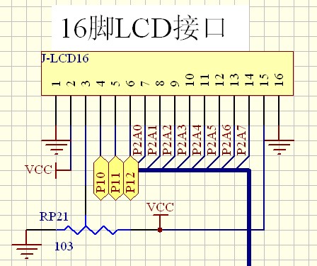
LCD 显示屏(LCD1602 液晶屏 (蓝屏)5V 带背光 1602 液晶屏)
http://item.taobao.com/item.htm?spm=a1z09.2.9.158.NjfIgL&id=23557856136&_u=t4u4an7fbfe
LCD1602 引脚说明如下:
第 1 脚:VSS 为地电源
第 2 脚:VDD 接 5V 正电源
第 3 脚:V0 为液晶显示器对比度调整端,接正电源时对比度最弱,接地电源时对比度最高
第 4 脚:RS 为寄存器选择,高电平时选择数据寄存器、低电平时选择指令寄存器。
第 5 脚:R/W 为读写信号线,高电平时进行读操作,低电平时进行写操作。当 RS 和 RW 共同为低电平时可以写入指令或者显示地址,当 RS 为低电平 RW 为高电平时可以读忙信号,当 RS 为高电平 RW 为低电平时可以写入数据。
第 6 脚:E 端为使能端,当 E 端由高电平跳变成低电平时,液晶模块执行命令。
第 7 ~ 14 脚:D0 ~ D7 为 8 位双向数据线。
第 15 脚:背光电源正极
第 16 脚:背光电源负极

这篇教程是带有 python 的,所以不用 make 了。而且管脚也是相同的。
http://www.raspberrypi-spy.co.uk/2012/07/16x2-lcd-module-control-using-python/
有一些警告信息
lcd.py:58: RuntimeWarning: This channel is already in use, continuing anyway.  Use GPIO.setwarnings(False) to disable warnings.
  GPIO.setup(LCD_E, GPIO.OUT)  # E
lcd.py:59: RuntimeWarning: This channel is already in use, continuing anyway.  Use GPIO.setwarnings(False) to disable warnings.
  GPIO.setup(LCD_RS, GPIO.OUT) # RS
lcd.py:60: RuntimeWarning: This channel is already in use, continuing anyway.  Use GPIO.setwarnings(False) to disable warnings.
  GPIO.setup(LCD_D4, GPIO.OUT) # DB4
lcd.py:61: RuntimeWarning: This channel is already in use, continuing anyway.  Use GPIO.setwarnings(False) to disable warnings.
  GPIO.setup(LCD_D5, GPIO.OUT) # DB5
lcd.py:62: RuntimeWarning: This channel is already in use, continuing anyway.  Use GPIO.setwarnings(False) to disable warnings.
  GPIO.setup(LCD_D6, GPIO.OUT) # DB6
lcd.py:63: RuntimeWarning: This channel is already in use, continuing anyway.  Use GPIO.setwarnings(False) to disable warnings.
  GPIO.setup(LCD_D7, GPIO.OUT) # DB7
这是因为没有对 GPIO 进行 clean 的动作,需要使用如下代码(来源:http://www.raspberrypi.org/forums/viewtopic.php?f=32&t=20034#p195972)
GPIO.cleanup()
所以最终代码看起来应该是这样的:https://github.com/xx7y7xx/rpi/blob/master/lcd.py
开始运行
sudo python lcd.py
但是 lcd 上始终没有显示东西。
开始寻找另外的教程。
关于如何调节 LCD,可以参考这里:https://learn.adafruit.com/drive-a-16x2-lcd-directly-with-a-raspberry-pi/wiring
后来又发现一篇讲的比较好的: https://learn.adafruit.com/character-lcd-with-raspberry-pi-or-beaglebone-black/overview
参考
- 电阻色环计算器 http://www.21ic.com/calculator/5sehuan.htm
- How Shift Registers Work https://www.youtube.com/watch?v=Z5iFTBJWz68